First we need to know about Diaphragm Constraint, Rigid & Semi-rigid diaphragm. Lets start-
Diaphragm Constraint: We know what are restraint joints (Supported individually) & constraint joints (Connected to each other so their translation & rotation happen together).
Diaphragm constraint is planar constraint connecting joints in a plane. Constraint joints can be connected in horizontal, vertical or any plane in 3d space, but Diaphragm constraint connects joints in single plane. For building analysis, we use diaphragm for horizontal floors that’s why we have to assign diaphragms along horizontal plane (floor) and we can not include any joint outside the horizontal plane into a diaphragm (For this-when we select all the joints of horizontal Plane & intermediate joints in stair landing to assign diaphragms, then we see warning in Etabs).
Diaphragm constraints exposes membrane behavior of a floor.
Rigid Diaphragm: Rigid diaphragms have infinite in-plane stiffness properties, and therefore they neither exhibit membrane deformation nor report the associated forces. A rigid diaphragm is where the in-plane stiffness is so large that all joints translate or rotate together. There is no elongation/strain developed. ETABS ties all nodes within the diaphragm extents to the center of rigidity of the system with infinite in-plane stiffness. The user has the option of detaching individual nodes from the diaphragm if they want. The user can also apply diaphragm directly to nodes instead of the entire floor area.
For rigid diaphragms in auto seismic case, the accidental eccentricity associated with auto seismic loading is concentrated and applied at the center of mass.
For rigid diaphragms in auto wind case, loading is applied at geometric centroid.
Semi-Rigid Diaphragm: Semi-rigid diaphragms simulate actual in-plane stiffness properties and behavior. In case of semi-rigid diaphragm, ETABS numerically models the in-plane stiffness to represent the actual diaphragm. So, if we model metal deck, it will use the stiffness of that metal deck. If we model concrete on metal deck, then it will consider greater stiffness (which is greater than metal deck alone). That’s why semi-rigid diaphragms are more realistic than rigid diaphragms. Semi-rigid diaphragms can be manually modeled with plates exhibiting plane stress.
For semi-rigid diaphragms in auto seismic case, accidental eccentricity is applied to every node.
For semi-rigid diaphragms in auto wind case, wind loads are distributed in 10 nodes, so that the summation of these forces with respect to centroid will be equivalent to lateral and torsional wind cases.
Now let’s discuss about the use of Diaphragms.
When we can use Rigid Diaphragm?
For most reinforced-concrete slab systems, in which the slab is sufficiently thick and membrane deformation due to lateral loading is negligible, rigid diaphragms can be assigned. In this case Rigid diaphragm produces results nearly identical to those of semi-rigid diaphragms. Rigid diaphragm has advantage of faster computation because it significantly reduces the stiffness matrix of the model as well as it reduces the eigen value problem.
For non-linear analysis of regular type of high-rise structure require lots of time to finish while using semi-rigid diaphragm. In that case we can use rigid diaphragm to reduce number of DOF that will reduce the analysis time & will reduce the size of model.
When we cannot use Rigid Diaphragm?
1.
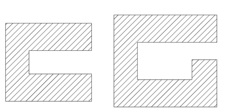
See above picture, in this type of floor or the floors having horizontal irregularity we cannot use Rigid Diaphragm. Because in this type of floor system actual in-plane stiffness is required to get realistic displacement of joints available in the disconnected end. Rigid diaphragm will change mode shape & dynamic behavior in this case rather than what it should be.
2.
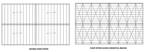
See above picture, in this type of floor having secondary beams or secondary bracing to control the transfer of diaphragm forces, if we apply rigid diaphragm then we will not be able to get any differential displacement between the joints. There will be no strain in shell or frame members that will not transfer any load from diaphragm forces. So here we can not apply rigid diaphragm.
3. If we assign Rigid diaphragm in case of transfer slabs (on top of which shear wall or columns start to the upper floors, take loads down & transfers through that slab) or heavy loaded slab then we will not be able to find the diaphragm shear in the slab. And also, we will get significant different mode shape & dynamic behavior of the structure. So, in these types of structure we have to use Semi-rigid diaphragm.
When we can use Semi-Rigid Diaphragm?
Actually, we can use semi-rigid diaphragm to almost all the floor system as it simulates actual in-plane stiffness properties and behavior. Semi-rigid diaphragms should be modeled when significant in-plane deformation does occur, or when required by code.
Different Diaphragm in different floor?
If you are going to model same type of diaphragm in all floors then you can define single diaphragm assignment like D1. Many of us define 20 diaphragms D1, D2…D20 for 20 floors in a building. That is waste of time. Because single (i.e. D1) diaphragm can work independently in different floors.
But if you want to assign different type of diaphragm like one floor Rigid another floor semi-rigid then you can define 2 types of diaphragm (D1, D2) one with Rigid & another with semi-rigid.
Another case, if we have two towers/buildings in a single model not connected to each other in floor levels then we have to assign different diaphragm identity D1 & D2 for each building in the same floor level, although the type of diaphragm can be same Rigid or Semi-Rigid.
When we can avoid using any diaphragm?
If we use cladding for applying lateral loads and we don’t bother about the diaphragm shear in our analysis then we can proceed analysis without modeling diaphragm.
Leave a Reply
You must be logged in to post a comment.